| Material specification | |
| Inside diameter (mm): | 80•100•120•150•180•200• |
| Inner surface | 0.5 mm nominal thickness Quality 1.4404 (AISI 316L stainless steel) |
| Surface thermal resistance m2K/W at 200°C |
Without insulation = 0.00 |
| Sealing ring |
Profiled ring seal with three black silicone sealing lips conforming to UNI EN 14241/1 |
| Roughness | 1 mm average value |
| Painting |
Modified silicone resin based paint, stably pigmentable, suitable for protecting installations exposed to the continuous or intermittent action of very high temperatures, such as chimneys, blast furnaces, cracking plants and so on. |
| General Information | |
| Installation | Internal Yes External NO it is not rain proof |
| Fields of application | Pipes, chimneys, smoke ducts, flues and manifolds connected to blown air, atmospheric, condensation and pressurised boilers, type B, C appliances, fireplaces, stoves, kitchen hoods, ovens and ventilation ducts |
| Permitted fuels | T200 Gas, Diesel oil, LPG, Pellets T600 Gas, Diesel oil, LPG, Pellets and Firewood |
| Conservation | In environments with a non-corrosive atmosphere |
| Product warranty | As per the 99/44/EC directive |
| Dangerous substances | At the temperatures declared, proved by test reports, no fumes develop due to the deterioration of the paint. In addition, the latter has suffered no deterioration or changes in colour. The paint only suffered a discoloration at 1000°C. |
|
Freezing-thawing resistance |
Meets UNI EN 1856-1 |
| Accidental contact | Protective shields must be used when surface temperature is greater than 85°C |
| Storage | Do not store the material near ferrous materials, premises must be dry and protected against the elements |
| Usage limits | Do not use stainless steel flue systems for premises such as laundries, dye houses, furriers, printer’s, beauty salons or where there are halogen or chromium vapours/fumes |
| Product designation as per the EN 1856-2 standard | Smoke duct |
| No. of the standard | EN 856-2 |
| Temperature level | T200 |
| Pressure level | P1 |
| Resistance to condensation | W |
| Resistance to corrosion | V2 |
| Thickness of the inner surface | L50010 |
| Resistance to fire from inside and distance from combustible materials | O(75) M |
| Product designation as per the EN 1856-2 standard: | Smoke duct |
| No. of the standard | EN 1856-2 |
| Temperature level | T450 |
| Pressure level | N1 |
| Resistance to condensation | D |
| Resistance to corrosion | V2 |
| Thickness of the inner surface | L50010 |
| Resistance to fire from inside and distance from combustible materials | G(800) M |
| Performance required according to the designation | ||
| Temperature level | T200
T450 |
working with a nominal fumes temperature at less than 200°C working with a nominal fumes temperature at less than 450°C |
| Pressure level | P1
N1 |
working with a positive and negative pressure up to 200Pa. Permitted loss less than 0.006 l/m2 working with a positive and negative pressure up to 40Pa. Permitted loss less than 2.0l/sm2 |
| Resistance to condensation | W
D |
working with moist and dry fumes working with dry fumes |
| Resistance to corrosion | V2 V2 | working with Gas-Diesel oil-LPG-Pellets-Firewood |
| Specification of the inner surface | L50 L50 | 1.4404 (AISI 316L stainless steel) |
| Thickness of the inner surface | 050 050 | 0.1 mm nominal thickness |
| Resistance to fire from inside | O
G |
not fire resistant from inside resistant to fire from inside |
| Distance from combustible materials | (75) M
(800) M |
(75)=minimum 75mm; M= value obtained with lab test (800)=minimum 800mm; M= value obtained with lab test |
INSTALLATION INSTRUCTIONS

- Position the elements as shown by the arrow printed on the label and on the piece.
- With use at T200_P1_W put the sealing ring in place on the female socket.
- The three lips of the sealing ring must be facing the inside of the pipe.
- Use some talcum powder or soap to make it easier to put the ring in place and also to prevent damaging it.
- If T600_N1_D is used, use the product without the sealing ring.
- Once the pieces are in place, mount and tighten the locking clamp on each join.
- Observe the compression loads and the non-vertical installations.
- Avoid the build-up of condensation or soot which could be the cause of corrosion. Also avoid horizontal sections; nonetheless install the elements with the longitudinal welding facing up (3% gradient).
ESSENTIAL FEATURES
Resistance to the wind load:
- Distance between wall brackets: NPD m
- Free length from the last bracket: NPD m
Compressive strength:
- Linear elements’ maximum load: 8m
- Maximum load of a straight fitting at 90°: 8m
- Maximum load of the wall chimney support: 8m
Note: these values refer to the worst conditions. For more info see (Mechanical Strength Table)
30m Tensile and bending strength (linear elements):
- Maximum load at traction (element connection means and chimney connections): 16m
- Non-vertical installations: max. 90°
- Non-vertical installations: distance between wall chimney supports = 2m
Traction and bending strength (non-linear elements):
- Non-vertical installations: NPD
FLUE SYSTEM MAINTENANCE
Scheduled maintenance carried out by qualified personnel:
- Unless standards dictate otherwise or different agreements are reached with the user, the following maintenance schedule is advisable:
- gaseous fuels: 1 / year;
- liquid fuels: 1 / 6 months;
- solid fuels: 1 / month.
- Clean the smoke duct with a soft plastic brush or sponge as well as the equipment compartment for pipe supply and ventilation, the inspection fitting and chimney and also make sure the smoke/fumes and condensates etc., are flowing freely.
SYSTEM COMPONENTS
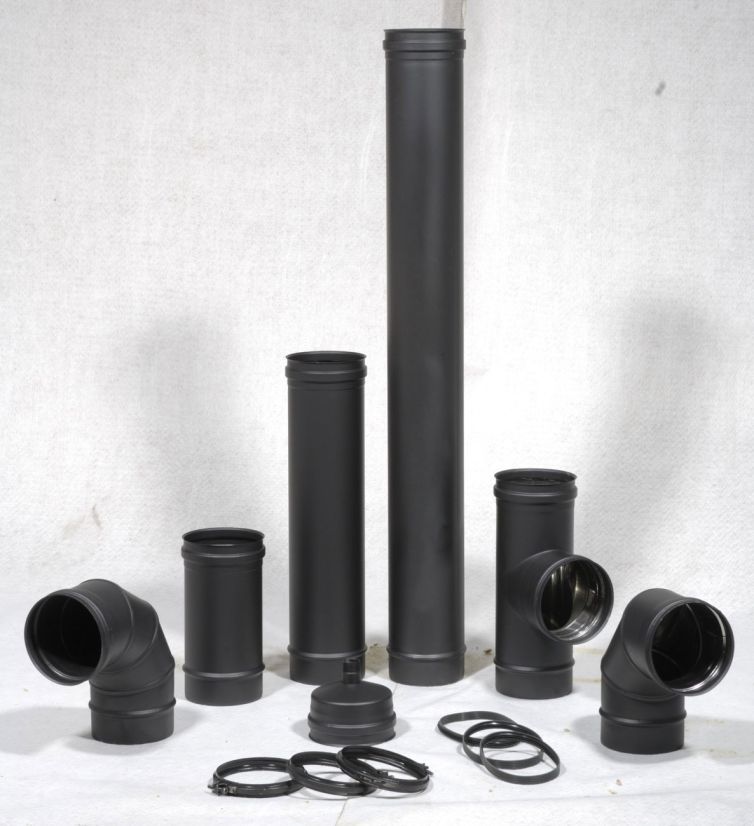
1 M LINEAR ELEMENT
995 mm high modular component to use on vertical or sub-horizontal sections. It must be applied as shown by the arrow printed on the label.
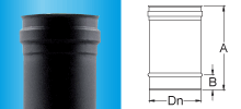
| Code | Dn | A | B |
| 4020 0080 | 80 | 995 | 40 |
| 4020 0100 | 100 | 995 | 40 |
| 4020 0120 | 120 | 995 | 40 |
| 4020 0150 | 150 | 995 | 40 |
| 4020 0180 | 180 | 995 | 40 |
| 4020 0200 | 200 | 995 | 40 |
0.5 M LINEAR ELEMENT
495 mm high modular component to use on vertical or sub-horizontal sections. It must be applied as shown by the arrow printed on the label.
| Code | Dn | A | B |
| 4015 0080 | 80 | 495 | 40 |
| 4015 0100 | 100 | 495 | 40 |
| 4015 0120 | 120 | 495 | 40 |
| 4015 0150 | 150 | 495 | 40 |
| 4015 0180 | 180 | 495 | 40 |
| 4015 0200 | 200 | 495 | 40 |
0.25 M LINEAR ELEMENT
245 mm high modular component to use on vertical or sub-horizontal sections. It must be applied as shown by the arrow printed on the label.
| Code | Dn | A | B |
| 4012 0080 | 80 | 245 | 40 |
| 4012 0100 | 100 | 245 | 40 |
| 4012 0120 | 120 | 245 | 40 |
| 4012 0150 | 150 | 245 | 40 |
| 4012 0180 | 180 | 245 | 40 |
| 4012 0200 | 200 | 245 | 40 |
BLACK SEALING RING T200
Necessary for sealing the pipe, chimney, flue and smoke duct. Colour black, designation T200 (250°C test temperature) and is not available with a 400 diameter. It conforms to standard UNI EN 14241/1 T200 W2 K2.

| Code | Dn | A |
| 4021 0080 | 80 | 12 |
| 4021 0100 | 100 | 12 |
| 4021 0120 | 120 | 12 |
| 4021 0150 | 150 | 12 |
| 4021 0180 | 180 | 12 |
| 4021 0200 | 200 | 12 |
LOCKING CLAMP
This component is necessary for the joining of elements; it guarantees greater stability to the system.

| Code | Dn | A | B |
| 4022 0080 | 80 | 20 | 82 |
| 4022 0100 | 100 | 20 | 102 |
| 4022 0120 | 120 | 20 | 122 |
| 4022 0150 | 150 | 20 | 152 |
| 4022 0180 | 180 | 20 | 182 |
| 4022 0200 | 200 | 20 | 202 |
45° CURVE
Thanks to this component the vertical axis of the chimney, flue, pipe or smoke duct can be slanted 45°.

| Code | Dn | A | B | C |
| 4024 0080 | 80 | 183 | 40 | 76 |
| 4024 0100 | 100 | 190 | 40 | 79 |
| 4024 0120 | 120 | 183 | 40 | 76 |
| 4024 0150 | 150 | 190 | 40 | 79 |
| 4024 0180 | 180 | 200 | 40 | 83 |
| 4024 0200 | 200 | 230 | 40 | 93 |
90° CURVE
The vertical axis can be slanted 90° with this component.
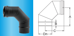
| Code | Dn | A | B | C |
| 4023 0080 | 80 | 175 | 40 | 175 |
| 4023 0100 | 100 | 175 | 40 | 175 |
| 4505 0120 | 120 | 180 | 40 | 180 |
| 4505 0150 | 150 | 190 | 40 | 190 |
| 4505 0180 | 180 | 215 | 40 | 215 |
| 4505 0200 | 200 | 233 | 40 | 233 |
90° STRAIGHT FITTING – FEMALE COUPLING
With this component the duct, chimney and flue can be connected at 90 to the smoke duct °. The peculiarity of this element is that it is made by extrusion meaning the female coupling can be welded without a seam.

| Code | Dn | A | B | A/2 |
| 4025 0080 | 80 | 328 | 40 | 164 |
| 4025 0100 | 100 | 328 | 40 | 164 |
| 4025 0120 | 120 | 328 | 40 | 164 |
| 4025 0150 | 150 | 328 | 40 | 164 |
| 4025 0180 | 180 | 495 | 40 | 247,5 |
| 4025 0200 | 200 | 495 | 40 | 247,5 |
for male graft COD 4546
EAVES PLATE
Component to place at the base of the chimney; its peculiarity is that it is made by swaging a flat disk. Moreover, the condensate discharge is made in stainless steel, ¾” thread and is welded in place.

| Code | Dn | A |
| 4026 0080 | 80 | 75 |
| 4026 0100 | 100 | 95 |
| 4026 0120 | 120 | 115 |
| 4026 0150 | 150 | 145 |
| 4026 0180 | 180 | 175 |
| 4026 0200 | 200 | 195 |
ADJUSTABLE WALL COLLAR
Used to anchor the chimney, flue and smoke duct to the wall. Its peculiarity is that the distance from the wall can be adjusted.

| Code | Dn | A | B |
| 4534 0080 | 80 | 140 | 200 |
| 4534 0100 | 100 | 150 | 210 |
| 4534 0120 | 120 | 160 | 220 |
| 4534 0150 | 150 | 175 | 235 |
| 4534 0180 | 180 | – | – |
| 4534 0200 | 200 | – | – |
PIPE WITH FLANGE
This component is used as a finishing flange when a hole is made for the pipe to go through. In this version the pipe is not the through type while art.

| Code | Dn | A | B | C |
| 4531 0080 | 80 | 80 | 162 | 80 |
| 4531 0100 | 100 | 100 | 182 | 80 |
| 4531 0120 | 120 | 120 | 202 | 80 |
| 4531 0150 | 150 | 150 | 232 | 80 |
| 4531 0180 | 180 | 180 | 262 | 80 |
| 4531 0200 | 200 | 200 | 282 | 80 |
SOCKET ELEMENT WITH FEMALE-FEMALE COUPLINGS
Linear component characterised by two female sockets.

| Code | Dn | A |
| 4529 0080 | 80 | 120 |
| 4529 0100 | 100 | 120 |
| 4529 0120 | 120 | 120 |
| 4529 0150 | 150 | 120 |
| 4529 0180 | 180 | 120 |
| 4529 0200 | 200 | 120 |
MAIN FEATURES
- Inner surface in 0.5mm thick AISI 316L BA stainless steel;
- Matt dark grey (black) paint with silicone component resistant to high temperatures (1000°C);
- High resistance to corrosion;
- Complete range (80-200 mm diameters).

MAIN FEATURES
- Inner surface in 0.5mm thick AISI 316L BA stainless steel;
- Matt dark grey (black) paint with silicone component resistant to high temperatures (1000°C);
- High resistance to corrosion;
- Complete range (80-200 mm diameters).
| Material specification | |
| Inside diameter (mm): | 80•100•120•150•180•200• |
| Inner surface | 0.5 mm nominal thickness Quality 1.4404 (AISI 316L stainless steel) |
| Surface thermal resistance m2K/W at 200°C |
Without insulation = 0.00 |
| Sealing ring |
Profiled ring seal with three black silicone sealing lips conforming to UNI EN 14241/1 |
| Roughness | 1 mm average value |
| Painting |
Modified silicone resin based paint, stably pigmentable, suitable for protecting installations exposed to the continuous or intermittent action of very high temperatures, such as chimneys, blast furnaces, cracking plants and so on. |
| General Information | |
| Installation | Internal Yes External NO it is not rain proof |
| Fields of application | Pipes, chimneys, smoke ducts, flues and manifolds connected to blown air, atmospheric, condensation and pressurised boilers, type B, C appliances, fireplaces, stoves, kitchen hoods, ovens and ventilation ducts |
| Permitted fuels | T200 Gas, Diesel oil, LPG, Pellets T600 Gas, Diesel oil, LPG, Pellets and Firewood |
| Conservation | In environments with a non-corrosive atmosphere |
| Product warranty | As per the 99/44/EC directive |
| Dangerous substances | At the temperatures declared, proved by test reports, no fumes develop due to the deterioration of the paint. In addition, the latter has suffered no deterioration or changes in colour. The paint only suffered a discoloration at 1000°C. |
|
Freezing-thawing resistance |
Meets UNI EN 1856-1 |
| Accidental contact | Protective shields must be used when surface temperature is greater than 85°C |
| Storage | Do not store the material near ferrous materials, premises must be dry and protected against the elements |
| Usage limits | Do not use stainless steel flue systems for premises such as laundries, dye houses, furriers, printer’s, beauty salons or where there are halogen or chromium vapours/fumes |
| Product designation as per the EN 1856-2 standard | Smoke duct |
| No. of the standard | EN 856-2 |
| Temperature level | T200 |
| Pressure level | P1 |
| Resistance to condensation | W |
| Resistance to corrosion | V2 |
| Thickness of the inner surface | L50010 |
| Resistance to fire from inside and distance from combustible materials | O(75) M |
| Product designation as per the EN 1856-2 standard: | Smoke duct |
| No. of the standard | EN 1856-2 |
| Temperature level | T450 |
| Pressure level | N1 |
| Resistance to condensation | D |
| Resistance to corrosion | V2 |
| Thickness of the inner surface | L50010 |
| Resistance to fire from inside and distance from combustible materials | G(800) M |
| Performance required according to the designation | ||
| Temperature level | T200
T450 |
working with a nominal fumes temperature at less than 200°C working with a nominal fumes temperature at less than 450°C |
| Pressure level | P1
N1 |
working with a positive and negative pressure up to 200Pa. Permitted loss less than 0.006 l/m2 working with a positive and negative pressure up to 40Pa. Permitted loss less than 2.0l/sm2 |
| Resistance to condensation | W
D |
working with moist and dry fumes working with dry fumes |
| Resistance to corrosion | V2 V2 | working with Gas-Diesel oil-LPG-Pellets-Firewood |
| Specification of the inner surface | L50 L50 | 1.4404 (AISI 316L stainless steel) |
| Thickness of the inner surface | 050 050 | 0.1 mm nominal thickness |
| Resistance to fire from inside | O
G |
not fire resistant from inside resistant to fire from inside |
| Distance from combustible materials | (75) M
(800) M |
(75)=minimum 75mm; M= value obtained with lab test (800)=minimum 800mm; M= value obtained with lab test |
INSTALLATION INSTRUCTIONS

- Position the elements as shown by the arrow printed on the label and on the piece.
- With use at T200_P1_W put the sealing ring in place on the female socket.
- The three lips of the sealing ring must be facing the inside of the pipe.
- Use some talcum powder or soap to make it easier to put the ring in place and also to prevent damaging it.
- If T600_N1_D is used, use the product without the sealing ring.
- Once the pieces are in place, mount and tighten the locking clamp on each join.
- Observe the compression loads and the non-vertical installations.
- Avoid the build-up of condensation or soot which could be the cause of corrosion. Also avoid horizontal sections; nonetheless install the elements with the longitudinal welding facing up (3% gradient).
ESSENTIAL FEATURES
Resistance to the wind load:
- Distance between wall brackets: NPD m
- Free length from the last bracket: NPD m
Compressive strength:
- Linear elements’ maximum load: 8m
- Maximum load of a straight fitting at 90°: 8m
- Maximum load of the wall chimney support: 8m
Note: these values refer to the worst conditions. For more info see (Mechanical Strength Table)
30m Tensile and bending strength (linear elements):
- Maximum load at traction (element connection means and chimney connections): 16m
- Non-vertical installations: max. 90°
- Non-vertical installations: distance between wall chimney supports = 2m
Traction and bending strength (non-linear elements):
- Non-vertical installations: NPD
FLUE SYSTEM MAINTENANCE
Scheduled maintenance carried out by qualified personnel:
- Unless standards dictate otherwise or different agreements are reached with the user, the following maintenance schedule is advisable:
- gaseous fuels: 1 / year;
- liquid fuels: 1 / 6 months;
- solid fuels: 1 / month.
- Clean the smoke duct with a soft plastic brush or sponge as well as the equipment compartment for pipe supply and ventilation, the inspection fitting and chimney and also make sure the smoke/fumes and condensates etc., are flowing freely.
SYSTEM COMPONENTS
1 M LINEAR ELEMENT
995 mm high modular component to use on vertical or sub-horizontal sections. It must be applied as shown by the arrow printed on the label.

| Code | Dn | A | B |
| 4020 0080 | 80 | 995 | 40 |
| 4020 0100 | 100 | 995 | 40 |
| 4020 0120 | 120 | 995 | 40 |
| 4020 0150 | 150 | 995 | 40 |
| 4020 0180 | 180 | 995 | 40 |
| 4020 0200 | 200 | 995 | 40 |
0.5 M LINEAR ELEMENT
495 mm high modular component to use on vertical or sub-horizontal sections. It must be applied as shown by the arrow printed on the label.
| Code | Dn | A | B |
| 4015 0080 | 80 | 495 | 40 |
| 4015 0100 | 100 | 495 | 40 |
| 4015 0120 | 120 | 495 | 40 |
| 4015 0150 | 150 | 495 | 40 |
| 4015 0180 | 180 | 495 | 40 |
| 4015 0200 | 200 | 495 | 40 |
0.25 M LINEAR ELEMENT
245 mm high modular component to use on vertical or sub-horizontal sections. It must be applied as shown by the arrow printed on the label.
| Code | Dn | A | B |
| 4012 0080 | 80 | 245 | 40 |
| 4012 0100 | 100 | 245 | 40 |
| 4012 0120 | 120 | 245 | 40 |
| 4012 0150 | 150 | 245 | 40 |
| 4012 0180 | 180 | 245 | 40 |
| 4012 0200 | 200 | 245 | 40 |
BLACK SEALING RING T200
Necessary for sealing the pipe, chimney, flue and smoke duct. Colour black, designation T200 (250°C test temperature) and is not available with a 400 diameter. It conforms to standard UNI EN 14241/1 T200 W2 K2.

| Code | Dn | A |
| 4021 0080 | 80 | 12 |
| 4021 0100 | 100 | 12 |
| 4021 0120 | 120 | 12 |
| 4021 0150 | 150 | 12 |
| 4021 0180 | 180 | 12 |
| 4021 0200 | 200 | 12 |
LOCKING CLAMP
This component is necessary for the joining of elements; it guarantees greater stability to the system.

| Code | Dn | A | B |
| 4022 0080 | 80 | 20 | 82 |
| 4022 0100 | 100 | 20 | 102 |
| 4022 0120 | 120 | 20 | 122 |
| 4022 0150 | 150 | 20 | 152 |
| 4022 0180 | 180 | 20 | 182 |
| 4022 0200 | 200 | 20 | 202 |
45° CURVE
Thanks to this component the vertical axis of the chimney, flue, pipe or smoke duct can be slanted 45°.

| Code | Dn | A | B | C |
| 4024 0080 | 80 | 183 | 40 | 76 |
| 4024 0100 | 100 | 190 | 40 | 79 |
| 4024 0120 | 120 | 183 | 40 | 76 |
| 4024 0150 | 150 | 190 | 40 | 79 |
| 4024 0180 | 180 | 200 | 40 | 83 |
| 4024 0200 | 200 | 230 | 40 | 93 |
90° CURVE
The vertical axis can be slanted 90° with this component.

| Code | Dn | A | B | C |
| 4023 0080 | 80 | 175 | 40 | 175 |
| 4023 0100 | 100 | 175 | 40 | 175 |
| 4505 0120 | 120 | 180 | 40 | 180 |
| 4505 0150 | 150 | 190 | 40 | 190 |
| 4505 0180 | 180 | 215 | 40 | 215 |
| 4505 0200 | 200 | 233 | 40 | 233 |
90° STRAIGHT FITTING – FEMALE COUPLING
With this component the duct, chimney and flue can be connected at 90 to the smoke duct °. The peculiarity of this element is that it is made by extrusion meaning the female coupling can be welded without a seam.

| Code | Dn | A | B | A/2 |
| 4025 0080 | 80 | 328 | 40 | 164 |
| 4025 0100 | 100 | 328 | 40 | 164 |
| 4025 0120 | 120 | 328 | 40 | 164 |
| 4025 0150 | 150 | 328 | 40 | 164 |
| 4025 0180 | 180 | 495 | 40 | 247,5 |
| 4025 0200 | 200 | 495 | 40 | 247,5 |
for male graft COD 4546
EAVES PLATE
Component to place at the base of the chimney; its peculiarity is that it is made by swaging a flat disk. Moreover, the condensate discharge is made in stainless steel, ¾” thread and is welded in place.

| Code | Dn | A |
| 4026 0080 | 80 | 75 |
| 4026 0100 | 100 | 95 |
| 4026 0120 | 120 | 115 |
| 4026 0150 | 150 | 145 |
| 4026 0180 | 180 | 175 |
| 4026 0200 | 200 | 195 |
ADJUSTABLE WALL COLLAR
Used to anchor the chimney, flue and smoke duct to the wall. Its peculiarity is that the distance from the wall can be adjusted.

| Code | Dn | A | B |
| 4534 0080 | 80 | 140 | 200 |
| 4534 0100 | 100 | 150 | 210 |
| 4534 0120 | 120 | 160 | 220 |
| 4534 0150 | 150 | 175 | 235 |
| 4534 0180 | 180 | – | – |
| 4534 0200 | 200 | – | – |
PIPE WITH FLANGE
This component is used as a finishing flange when a hole is made for the pipe to go through. In this version the pipe is not the through type while art.

| Code | Dn | A | B | C |
| 4531 0080 | 80 | 80 | 162 | 80 |
| 4531 0100 | 100 | 100 | 182 | 80 |
| 4531 0120 | 120 | 120 | 202 | 80 |
| 4531 0150 | 150 | 150 | 232 | 80 |
| 4531 0180 | 180 | 180 | 262 | 80 |
| 4531 0200 | 200 | 200 | 282 | 80 |
SOCKET ELEMENT WITH FEMALE-FEMALE COUPLINGS
Linear component characterised by two female sockets.

| Code | Dn | A |
| 4529 0080 | 80 | 120 |
| 4529 0100 | 100 | 120 |
| 4529 0120 | 120 | 120 |
| 4529 0150 | 150 | 120 |
| 4529 0180 | 180 | 120 |
| 4529 0200 | 200 | 120 |


